
Did You Know Your Oxygen Costs? Discover How Much You Could Save!
Discover how much you could save on oxygen costs with our insightful guide. Uncover potential…
This issue of Vapors will discuss the function of vaporizers and their output. The discussion will begin with a fictional scenario. Gabby, a healthy 40 lb. female border collie, was anesthetized to remove a lump from her leg. There was a crisis during the anesthetic procedure that resulted in post-anesthesia complications and required intensive care for 48 hours. As a result, the owners did not want to pay the ICU expenses and began pursuing the issue. The client requested to see the patient record and any service records for the anesthetic machine. The anesthetic record did not reveal anything that would explain the crisis. However, upon examination of the service record for the machine and vaporizer, it was noted that at 3%, the vaporizer was reading at 3.4%. It was observed from the anesthetic record that Gabby was anesthetized at 3% for a short time at the beginning of surgery.
The owners claim that because the vaporizer is not functioning properly, it caused the crisis. Is this a legitimate claim? It is not. Many people think if a vaporizer is set at 2%, the output is exactly 2%. That is not correct. Vaporizers operate within a certain tolerance. Most manufacturers have a +/- 10% tolerance on new vaporizers. Some have a tolerance of +/- 15%. Anesthesia service companies may have a +/- 20% tolerance. Dorsch and Dorsch state, “the average delivered concentration from the vaporizer shall not deviate from the set value by more than +/- 20% or +/- 5% of the maximum setting, whichever is greater, without back pressure”1. They are quoting from the ASTM anesthesia workstation standard. It is almost impossible for vaporizers to read exactly what is on the dial due to the way they function.
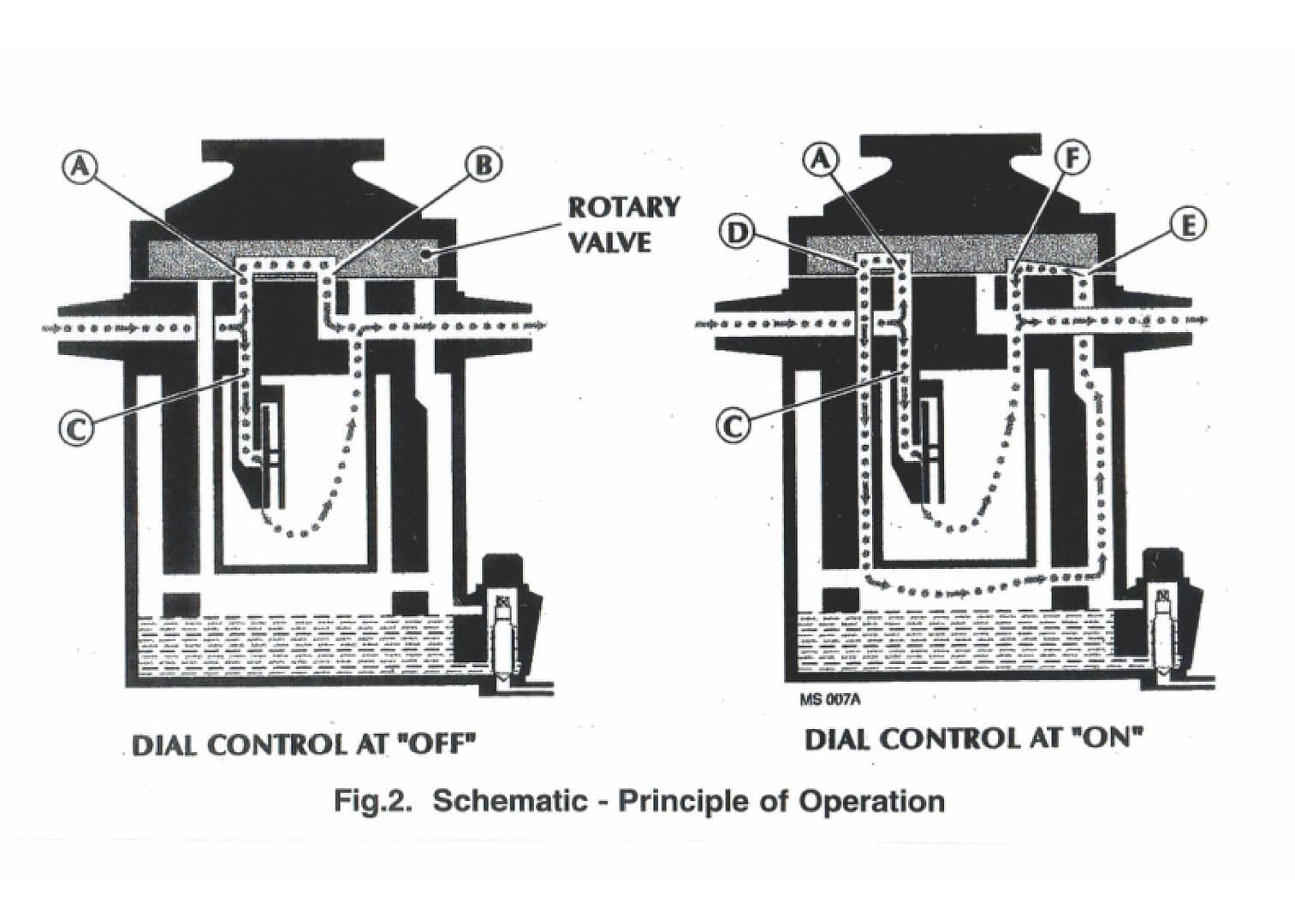
When the vaporizer is turned on, a small part of the flow is diverted into the sump to carry some of the vapor from the sump, which is then mixed with the remainder of the flow. If the oxygen flow is 1 liter per minute and the vaporizer is set to 1%, approximately 30 cc of the flow is diverted into the sump, through the wick, and then mixed back into the main flow (see Figure 2). As the setting on the dial is increased, more of the flow is diverted through the sump to carry more vapor from the sump (see Figure 1). The oxygen is diverted into the sump by a resistance to flow created by the thermostat. It is not hard to understand that observing an accurate reading would be very difficult; however, precise readings should still be expected. This means that if a vaporizer is checked and is reading +12%, that is what the vaporizer should read in subsequent years. A change from that indicates there may be a problem. Vetamac’s VICTOR database allows the service technician to look at the previous readings and make decisions about the function of a vaporizer.
The anesthetic vaporizer is the heart and soul of the anesthetic machine and with proper attention will provide many years of service. However, let’s remember that the depth of anesthesia and condition of the patient is not determined by observing the setting on the vaporizer but by observing the patient.
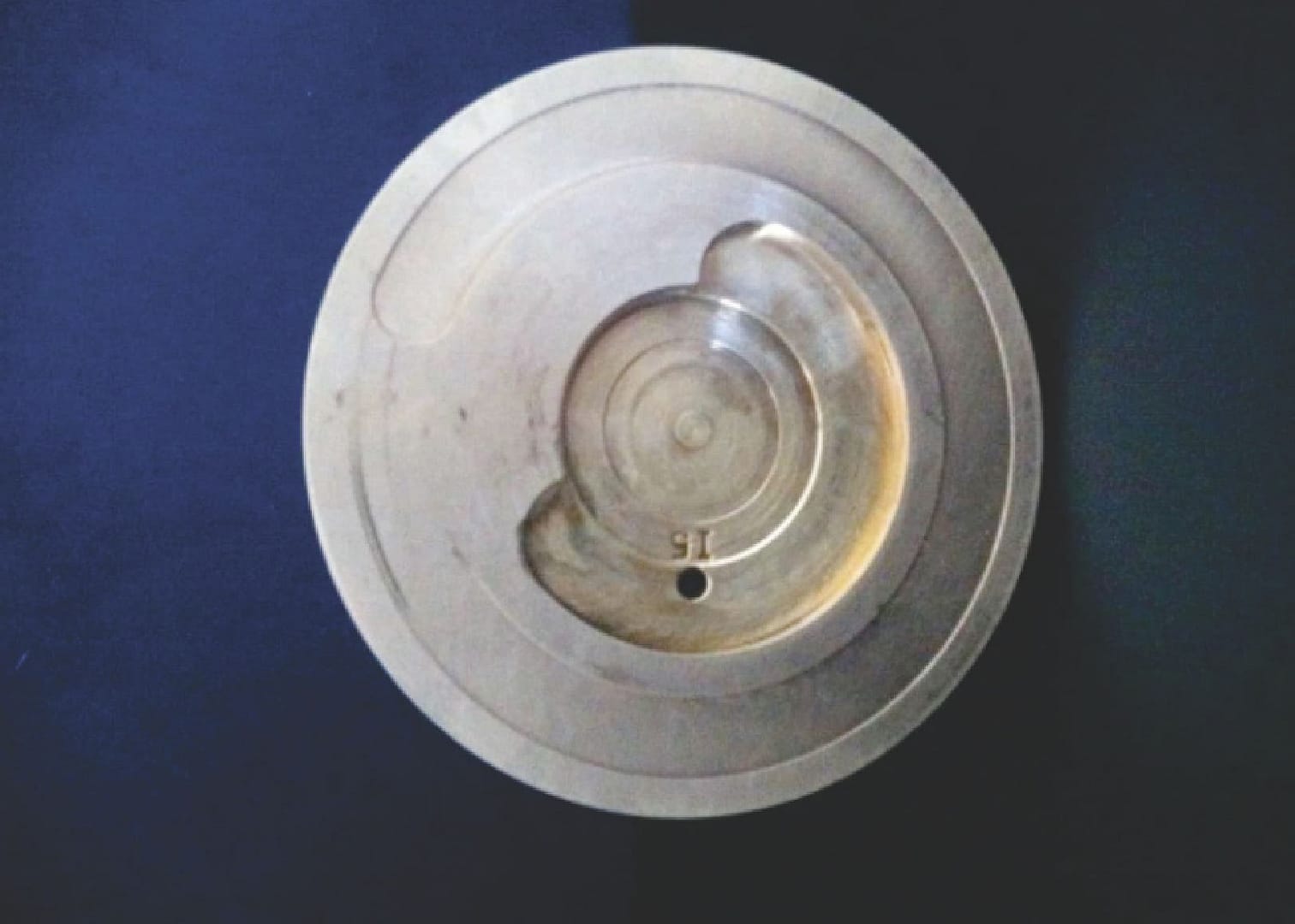
Figure 1: rotary valve from a Tec 3 style vaporizer. This is the rotary valve that the dial turns as the setting is changed. Note that starting at the top and going counter clockwise around the outside of the valve, the groove becomes deeper allowing more oxygen to flow through the sump thereby increasing the concentration.
Figure 2: The view on the left shows the vaporizer off with all the oxygen bypassing the vapor chamber through thermostat C and rotary valve passage A to rotary valve outlet B. The view on the right shows the vaporizer on with some of the oxygen bypassing through thermostat C and some passing through passage D (Bis closed) into the vapor chamber. It passes through calibrated channel E into vaporizer outlet F where it is mixed with bypassed oxygen from C.


Veterinary Specialist Articles