
Did You Know Your Oxygen Costs? Discover How Much You Could Save!
Discover how much you could save on oxygen costs with our insightful guide. Uncover potential…
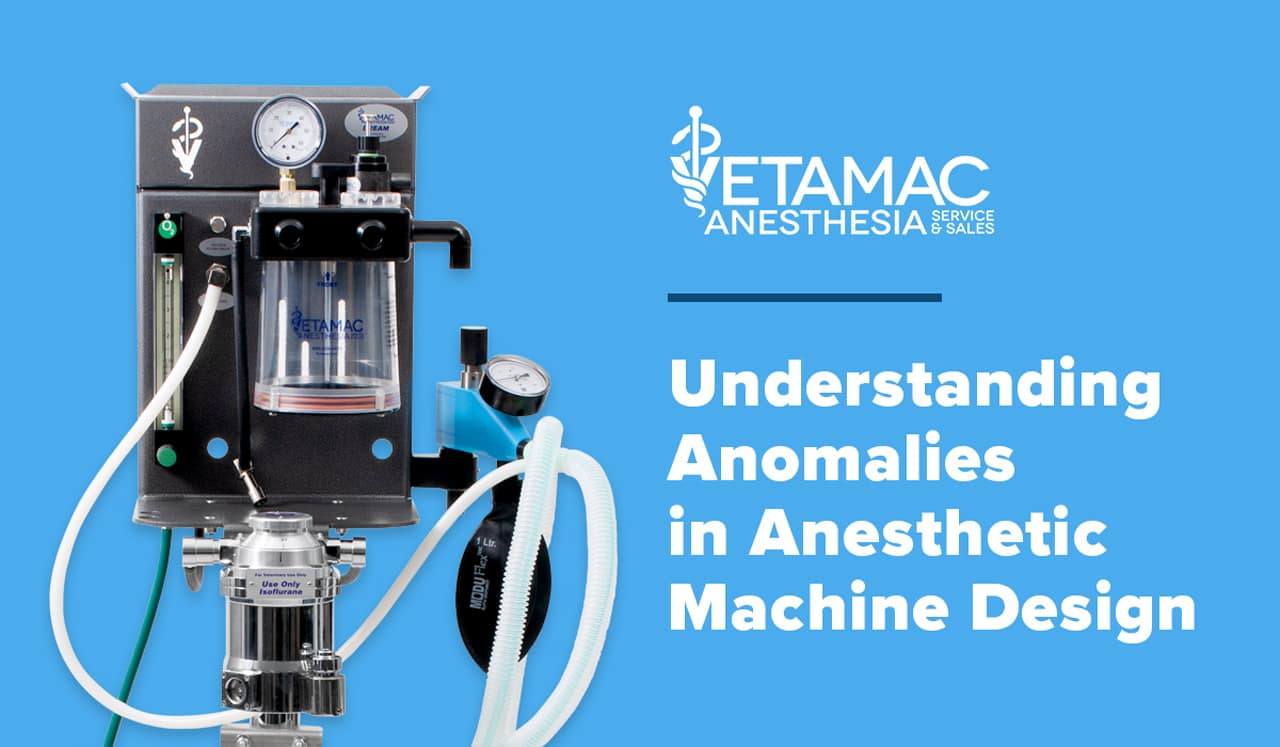
The next two issues of Vapors will discuss “anomalies” that are present in anesthetic machines. The first issue will deal with “congenital” anomalies which are present due to the characteristics in the design and manufacture of the machine. These anomalies will always be present. The second issue will deal with “acquired” anomalies resulting from exposure to environmental forces but can be prevented and corrected.
All anesthetic machines have a fresh gas or common gas outlet. This is the point in the circuit at which flow from the flowmeter and flush valve join and are then connected to the breathing circuit. Some machines have 15 mm female connections for the fresh gas and others have tubing that is connected directly to the breathing circuit. Regardless of the configuration of the fresh gas outlet there must be a proper connection to the breathing circuit.
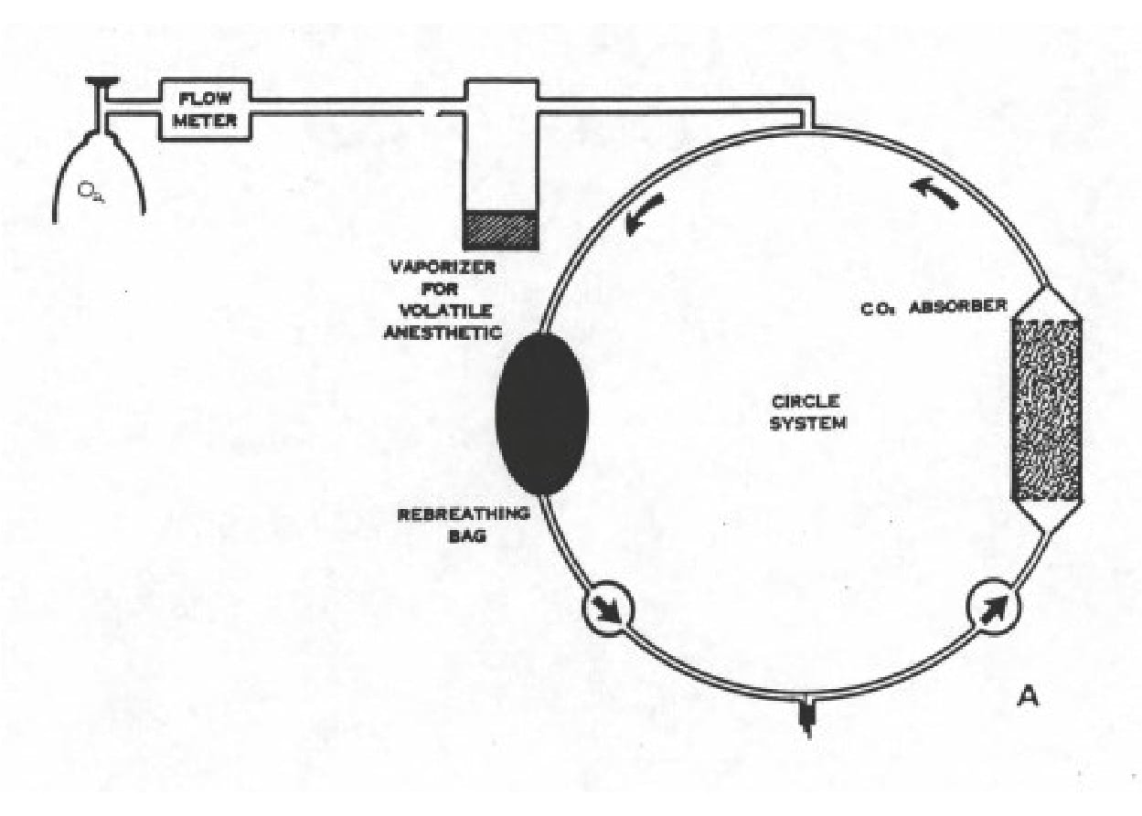
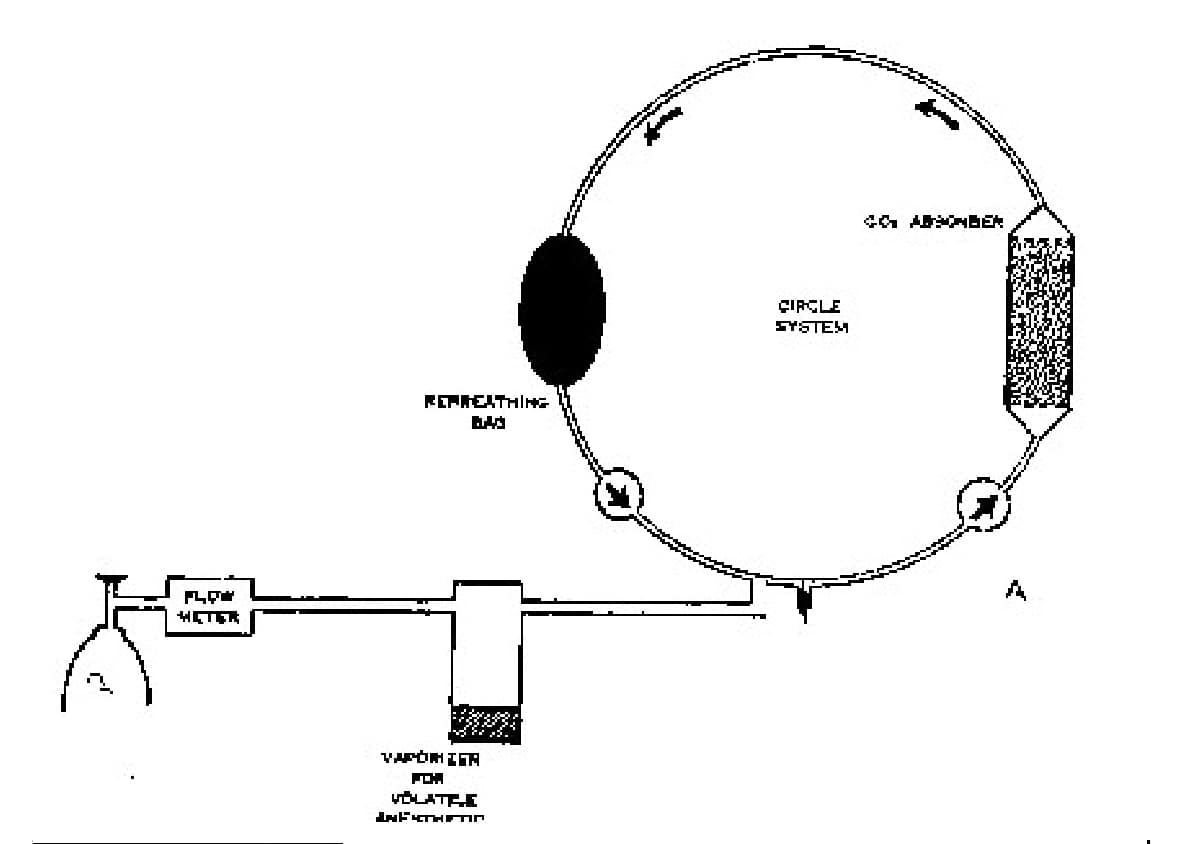
Although the plumbing and tubing connections are varied and the point of entrance is different among different machines, they all deliver fresh gas to the circuit. The point of entrance in the circuit can have an effect on the delivery of fresh gas to the circuit. Most machines have the entrance point between the one way valves (see figure lA). This means that between expiration and the next inspiration the fresh gas flow travels to the bag without passing the patient. On some machines the entrance point is on the patient side of the inspiratory valve. The fresh gas travels down the inspiratory tube to the Y piece then up through the expiratory tube and valve and then to the bag (see figure 1B).
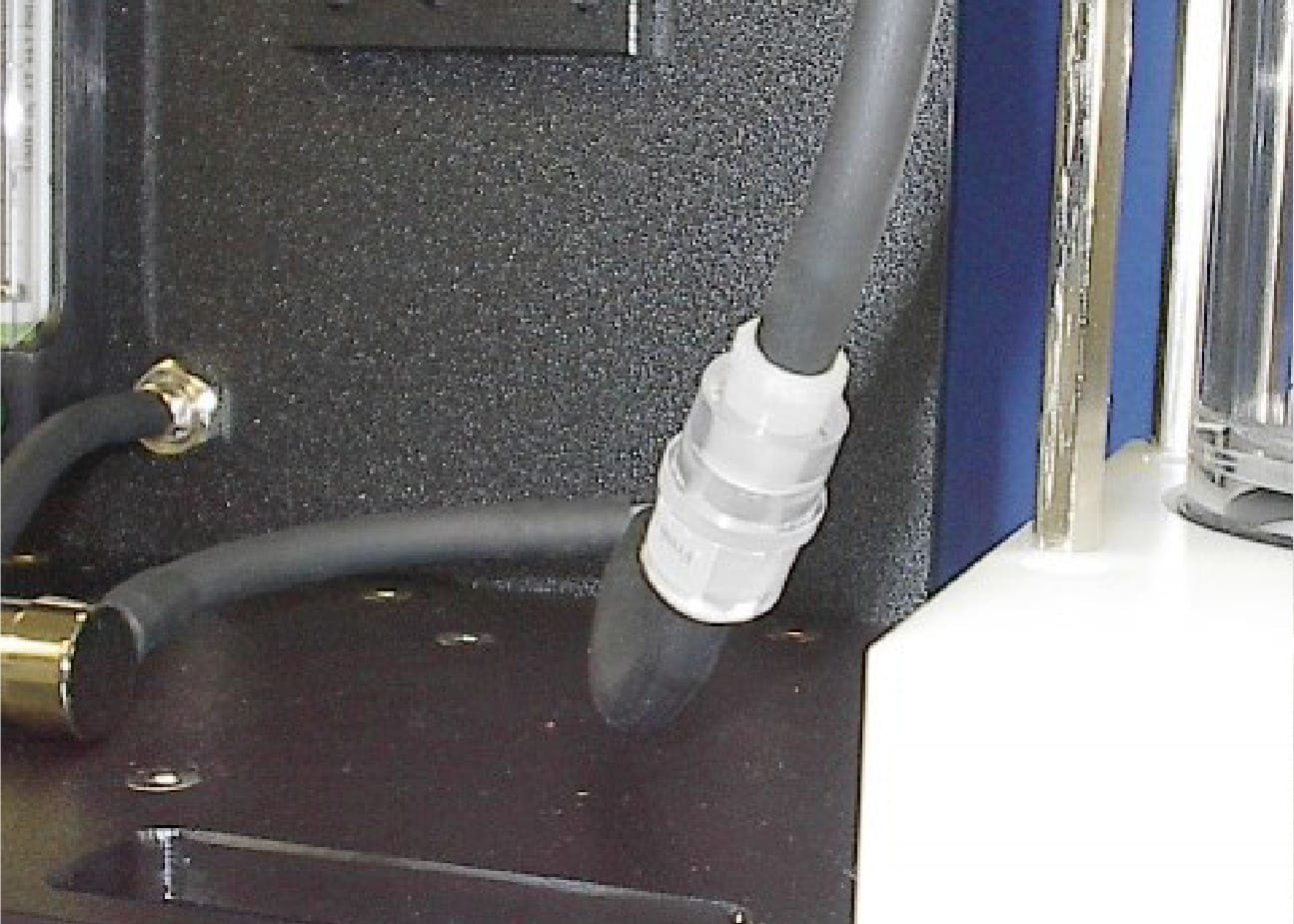
The configuration of the fresh gas flow also affects the method by which a non-rebreathing (NRB) system is connected. Many NRB systems have a 15mm male adapter that can be used on machines that have 15 mm adapters on the fresh gas outlet. If there is no suitable adapter, then the NRB must be connected by some other suitable method. One alternative is to install a 15mm connector in the fresh gas tubing that can be disconnected. The fresh gas tubing on the NRB can then be connected into the system (see figure 2).
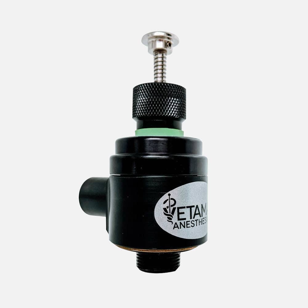
Not all pop off valves are adjustable pressure limiting (APL) valves because they are either open or closed and do not allow the user to adjust the pressure at which the valve opens and allows gas to escape. If a patient needs to be ventilated manually during a procedure it is very beneficial to have an APL valve because the desired pressure can be set. As the patient is ventilated the bag can be emptied by gently squeezing it until the desired amount of gas is left in the bag.
Some pop off and APL valves will allow gas to flow backwards through the valve. This is important only if a passive waste anesthetic gas evacuation system (WAGES) is used. When the system is removed from the patient WAG may then escape through the anesthetic machine into the room. lfan active WAGES is in use this will not occur.
The pop off valve is located in various positions in the circuit, depending on the type of machine. To maximize the removal of CO, by the pop off valve it should be located as close to the expiration limb of the breathing circuit as possible. Most often it is located with ergonomic considerations rather than removal of CO. Regardless of the style and location of the pop off valve, there must be a way to connect the valve to the WAGES – either passive or active.
The function of the one way valves is instrumental in eliminating dead space in the breathing circuit. Valves function in either a horizontal position or a vertical position with horizontal being preferable. If the valve discs are horizontal, gravity closes the valve. In the vertical position the disc must distort to open therefore it must be flexible. Over time this combination produces a tendency to become permanently distorted and the disc remains open. This will allow rebreathing of expired gases and problems with the anesthetic procedure. Most machines now have horizontal valves.
The location of the valves in the breathing circuit is not functionally important. It does, however, matter when coaxial breathing tubes are used since the inside tube must be connected to the inspiratory valve. All one way valves should be inspected periodically to insure they are functioning properly.
The discussion of the sodasorb canister includes the flow of gas through the canister and different styles of canisters. In some canisters the gas enters at the top and exits at the bottom or vice versa. If this is the case the canister will have an open top and a perforated bottom. It also means there must be seals on both the top and bottom which increases the occurrence of leaks since it is easy for soda sorb granules and dust to lodge in the bottom seal. Since the flow is in one direction there is probably less opportunity for channeling of the gas through the canister.
In other canisters the gas enters at the top and flows through the soda sorb and through a false bottom or around a baffle. It then travels back up through a center tube or the soda sorb on the other side of the baffle. The advantage of this canister is that it has only one seal at the top and soda sorb is less likely to lodge in the seal and create a leak. There is the potential for channeling of the gases in canisters that contain a baffle. There also may be a guide pin that needs to be properly aligned in the canisters that contain a baffle. Some canisters are made to accept pre-packed containers of soda sorb. Bulk soda sorb must be used in all other styles of canisters.
The next issue of Vapors will discuss acquired anomalies.


Veterinary Specialist Articles